Protocol
Protocol
Documentation on BIDS and iEEG-BIDS Data Conversion
The Brain Integrated Resource for Human Anatomy and Intracranial Neurophysiology (B(RAIN)ˆ2) is designed to provide standardized and integrated neuroimaging and neurophysiological data from participants in intracranial neurophysiological research. This resource provides transformed and preprocess neuroimaging and electrophysiological datasets. It includes high-resolution pre-, post-, and intraoperative neuroimaging, along with intracranial electrophysiological recordings from patients undergoing functional neurosurgical interventions. By utilizing standardized preprocessing techniques and spatial integration, B(RAIN)ˆ2 enhances the conduct of larger-scale studies, aiming to increase the utility of this unique dataset.
This document offers a comprehensive overview of the categorization and preprocessing methodologies for neuroimaging and electrophysiological recording (Fig. 1).
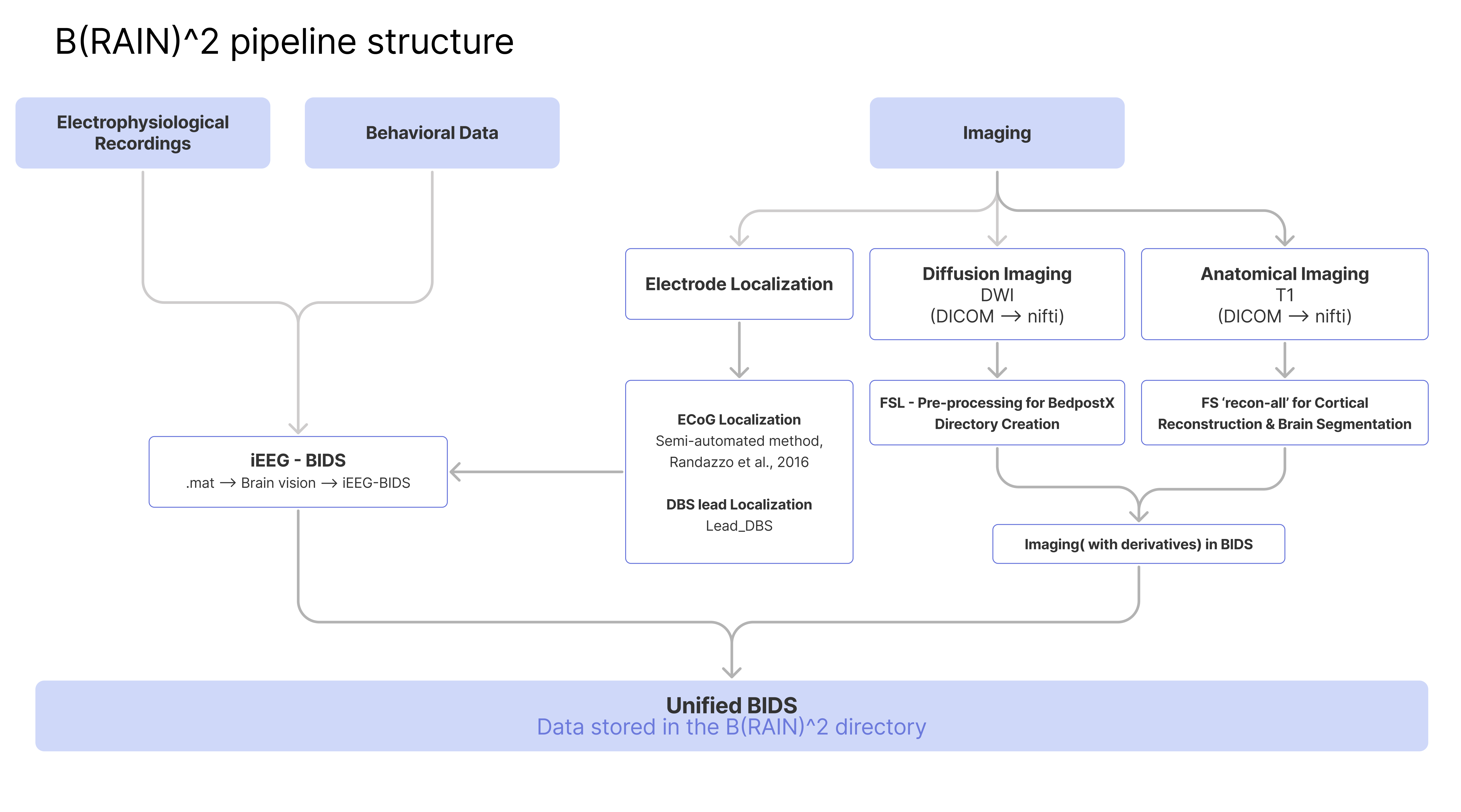
Figure 1.
illustrates the comprehensive process of preprocessing electrophysiology and imaging data as part of the B(RAIN)ˆ2 framework.1. Neuroimaging Processing
The neuroimaging data utilized in the preprocessing and localization phases of the B(RAIN)ˆ2 pipeline include preoperative MRI scans, including T1-weighted imaging (T1W), T2-weighted imaging (T2W), Fast Gray Matter Acquisition T1 Inversion Recovery (FGATIR), and Diffusion Weighted Imaging (DWI). Depending on the protocol of each center, either O-arm intraoperative CT scan imaging or intraoperative fluoroscopy imaging is employed to provide intraoperative imaging during surgery, which is used for lead localization. Furthermore, the pipeline incorporates pre- and postoperative axial Computed Tomography (CT) scans with 1mm slices for detailed bone and tissue density. As data is integrated from multiple centers, sequences may vary across some datasets.
Neuroimaging data organization and preprocessing are streamlined into three stages:
1) Preprocessing and conversion to Brain Imaging Data Structure (BIDS)[1]
2) Electrocorticography (ECoG) localization
3) Deep Brain Stimulation (DBS) lead localization
All neuroimaging data are fully anonymized during DICOM to NIfTI conversion and further processed for privacy protection with pydeface[2], ensuring the removal of facial features from MRI images.
1.1 BIDS data conversion
A systematic approach is essential to convert MRI data from the Digital Imaging and Communications in Medicine (DICOM)[3] format to BIDS, given that BIDS serves as the standard for organizing and describing neuroimaging data. Initially, it is recommended to visualize the DICOM data using tools like Onis DICOM viewer, version 2.6 (manufactured by Digitalcore Co. Ltd. Tokyo, Japan), Horos viewer, or Osirix viewer[4, 5]. Subsequently, it is crucial to ensure that DICOM files are methodically organized within a structured directory (Fig. 2). Leveraging MATLAB (The MathWorks Inc., Natick, MA, USA; 2023), the dcm2nii command (Li, X. (2023). dicm2nii. MATLAB Central File Exchange) can be employed to transition DICOM files to the Neuroimaging Informatics Technology Initiative (NIfTI) format [6, 7]. Notably, this procedure caters to all sessions across subjects and should be initiated within the root directory housing the DICOM data. Post-conversion, the BIDS-validator should be used to verify the dataset's compliance with the BIDS standard, addressing any inconsistencies flagged by the validator. Additionally, it's imperative to generate the requisite JavaScript Object Notation (JSON) files, which encapsulate the acquisition parameters, ensuring their placement alongside the NIfTI files. Once the data successfully passes the validation, it signifies the proficient conversion of the MRI data to the BIDS format (Fig. 2)
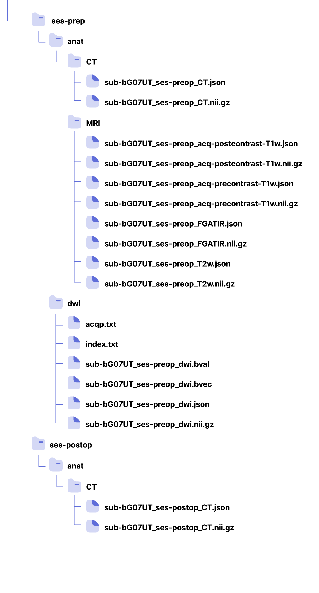
Figure 2.
Schematic of Pre- and Post-Operative Imaging Directories Organized According to the BIDS Standard for the Database.1.1.1 DWI Data Preprocessing and Standardization
For diffusion-weighted imaging, we leveraged the FMRIB Software Library's (FSL) version 6 (FMRIB Analysis Group, University of Oxford, 2023) capabilities[8]. This platform was instrumental in the preprocessing and primary processing of the DWI data, ensuring it was optimally prepared for detailed neuroimaging analysis (Fig. 3).
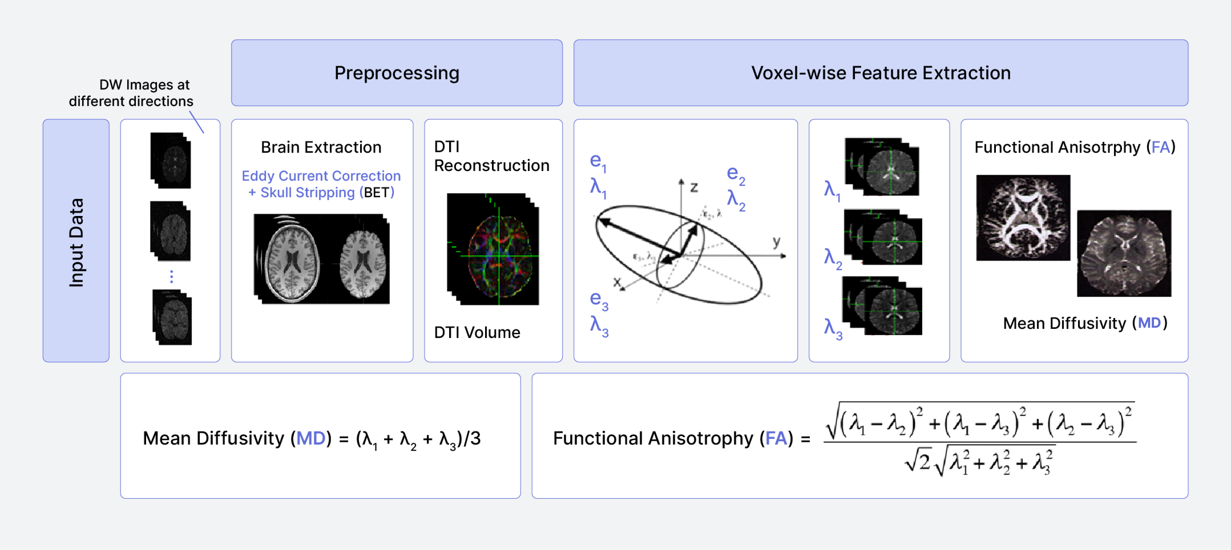
Figure 3.
The pipeline of DWI data analysis.In the preprocessing of DWI data using FSL, each subject's data was organized in individual directories. The preprocessing steps were performed to prepare the DWI data for advanced analysis, setting the groundwork for potential BedpostX processing. Brain tissue was isolated from the DWI images using the Brain Extraction Tool (BET), a pivotal step for accurate registration. Corrections for eddy current distortions and subject motion were applied using the eddy tool, mitigating the effects of magnetic field inhomogeneities. A gradient table encompassing the directional information and b-values from the DWI acquisition was prepared to facilitate the accurate interpretation of diffusion properties. The diffusion tensor model was fitted to the preprocessed data using dtifit, yielding metrics such as Fractional Anisotropy (FA) and Mean Diffusivity (MD). Maps of FA and MD were generated using 'fslmaths' from the output of 'dtifit,' providing quantitative insight into the diffusion properties within the brain. (Fig. 4).
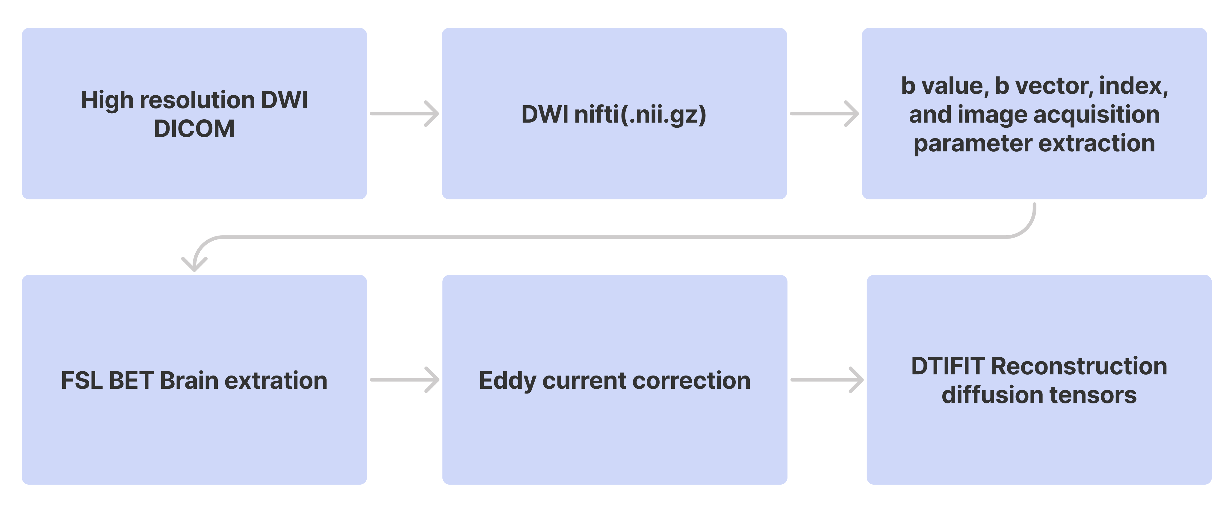
Figure 4.
Sequential Workflow of Diffusion Image Processing using FSL.1.2 ECoG electrode localization
Electrode localization is a critical component of electrophysiological studies. By accurately determining the coordinates of electrodes within a subject's native and Montreal Neurological Institute (MNI) neuroimaging spaces, we can pinpoint the precise neuroanatomical origins of electrophysiological recordings. Such precision is vital for rigorous neuroanatomical and electrophysiological evaluations.
Within the B(RAIN)ˆ2 pipeline, we perform electrode localization for both the DBS leads targeting deep brain nuclei electrophysiological recordings and the intraoperative ECoG electrodes designated for cortical recordings.
1.2.1 ECoG localization using intraoperative fluoroscopy images
For ECoG localization using fluoroscopy images, we employ a novel semi-automatic interface[10]. This tool facilitates localization by utilizing intraoperative fluoroscopy images of temporary ECoGs, in conjunction with routine clinical imaging techniques, including preoperative anatomical MRI and both pre- and postoperative CT scans (Fig. 6).
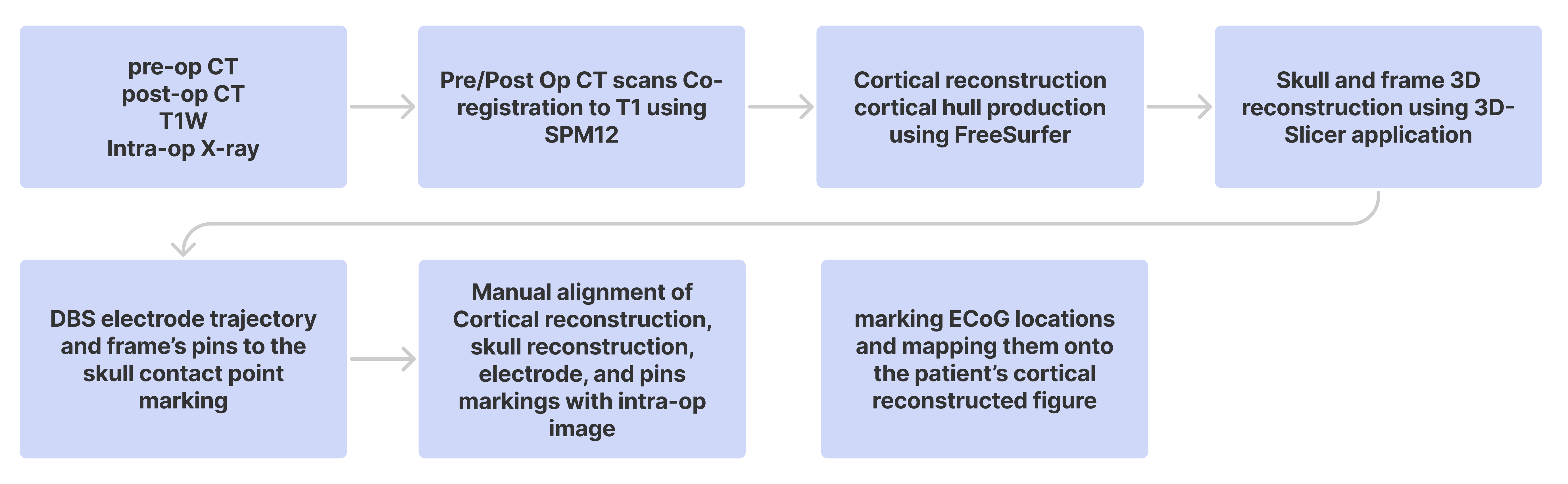
Figure 5.
Workflow depicting the sequential process of ECoG localization using the semi-automatic interface, as described by Randazzo et al. (2016).Building upon each subject's previously established BIDS directory, we further employ the anatomical T1W MRI in NIfTI format and its FreeSurfer (FS) derivative. Both the pre-and postoperative CT images undergo conversion to the NIfTI format using the dcm2nii command. Once converted, the preoperative CT is coregistered with the postoperative MRI through the normalized mutual information method, executed within the Statistical Parameter Mapping (SPM) package (SPM12, http://www.fil.ion.ucl.ac.uk/ ). The accuracy of this registration is then verified for each subject using the 'check registration' function in SPM12.
Utilizing a custom graphical user interface within MATLAB software, we visualized DBS electrode tract locations on the postoperative CT on a slice-by-slice basis. These tracts were distinctly marked along their entire length, focusing on every alternate axial slice with a 1 mm spacing. This interface also facilitated the marking of the tips of the four pins on the stereotactic frame — these pins secure the frame to the patient's head — as highlighted on the pre-operative CT slice images (Fig. 6).
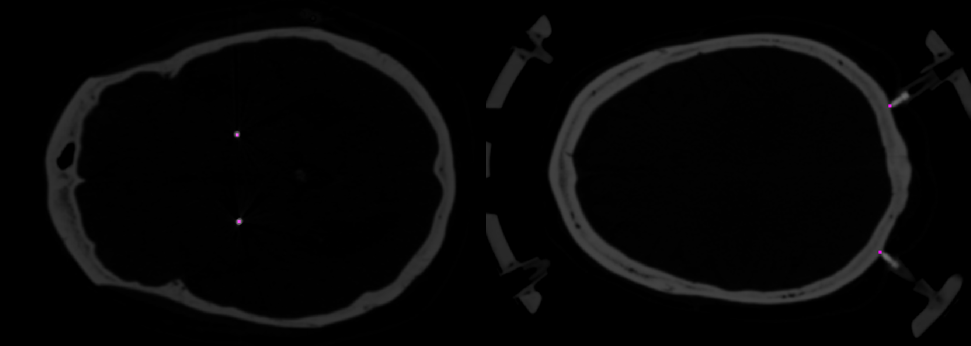
Figure 6.
Localization marks for DBS electrode tracts on the postoperative CT and stereotactic frame pins on the preoperative CT, integral to the ECoG localization procedure. Violet dots indicate electrode and pin locations.The coregistered and resliced CT images were imported into the 3D Slicer software (version 5.2.2, 2023) for rendering into a three-dimensional surface [11]. Intensity threshold and smoothing parameters were adjusted to selectively display the skull and the stereotactic frame, with particular emphasis on visualizing the pins and their contact points with the skull. Subsequently, this surface was exported as a Wavefront object (OBJ file) for visualization in MATLAB as a tessellated surface (Fig. 7).
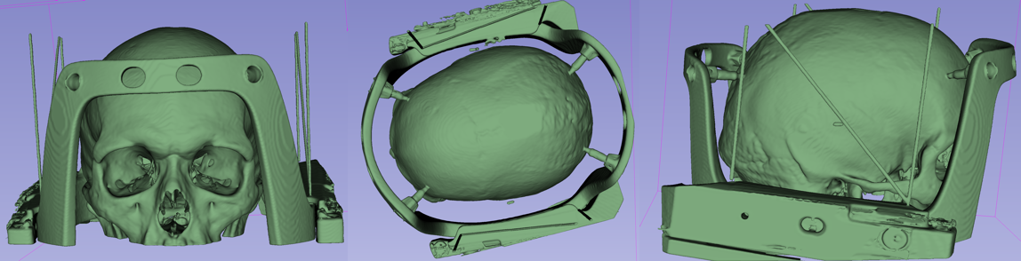
Figure 7.
Three-dimensional reconstruction of the skull surface and attached stereotactic frame, derived from preoperative CT images using 3D Slicer software (version 5.2.2, 2023)Coregistered cortical and skull surfaces were imported into a custom MATLAB interface alongside marked DBS electrode paths and stereotactic frame pin locations. The 2D intraoperational fluoroscopic image demonstrating the ECoG location on the cortical surface was positioned behind these surfaces, and the skull surface was adjusted to align with the fluoroscopic image using MATLAB's camera toolbox. Further adjustments optimized the alignment of landmarks between CT/MRI surfaces and the fluoroscopic image, with the alignment process facilitated by modifying the transparency and visibility of overlaid surfaces and landmarks. Lastly, the coordinates of each electrode will be reported in the subject's native space (Fig. 9).
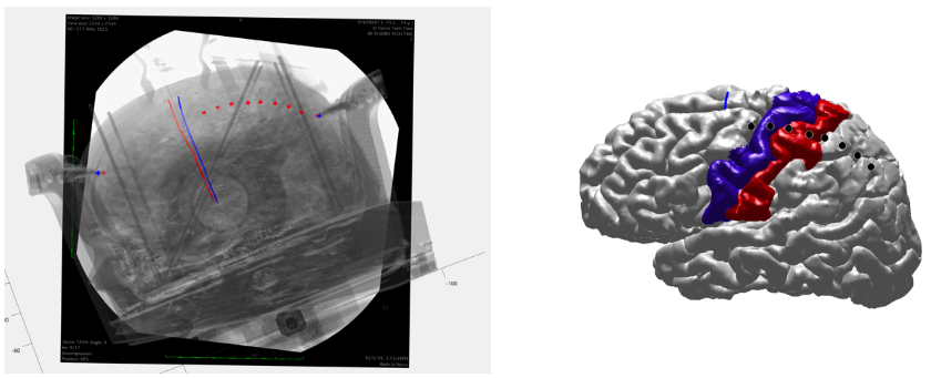
Figure 8.
Three-dimensional reconstruction of the skull surface and attached stereotactic frame, derived from preoperative CT images using 3D Slicer software (version 5.2.2, 2023)1.2.2 ECoG localization using O-arm images
When available, O-arm imaging significantly enhances the precision of ECoG localization. This section outlines the fundamental approach to localizing ECoG with O-arm imaging, aligning closely with methodologies employed in fluoroscopy imaging and utilizing similar platforms for consistency (Fig. 9).

Figure 9.
Workflow Depicting the Sequential Steps in ECoG Localization Enhanced by O-arm Imaging.Following the coregistration of the O-arm image with the subject's anatomical T1-weighted (T1W) image, the 3D Slicer software is utilized for a 3D reconstruction of the skull and the ECoG strip in situ. The process leverages the axial view to precisely remove skull segments adjacent to the ECoG placement area and attenuate noise from the ECoG electrodes. This careful approach is crucial for the clear visualization of the ECoG strip within the subject's anatomical context, ensuring its accurate alignment with the coregistered O-arm image, which is essential for precise electrode localization (Fig. 10).
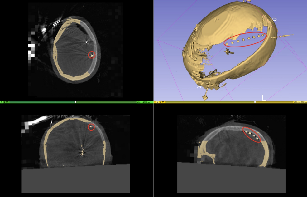
Figure 10.
Depicts the skull removal near the in situ ECoG strip and noise reduction from the strip, creating a unified 3D ECoG and skull model within the same anatomical space. Guided by multiple views for accurate ECoG localization, red circles highlight the strip's position.The reconstructed cortical surface and 3D skull, with the ECoG strip in situ, were imported into a custom MATLAB interface. Utilizing the reconstructed ECoG strip, the location of each channel on the cortical surface is pinpointed. Finally, the coordinates of each electrode are reported in the subject's native space (fig. 11)
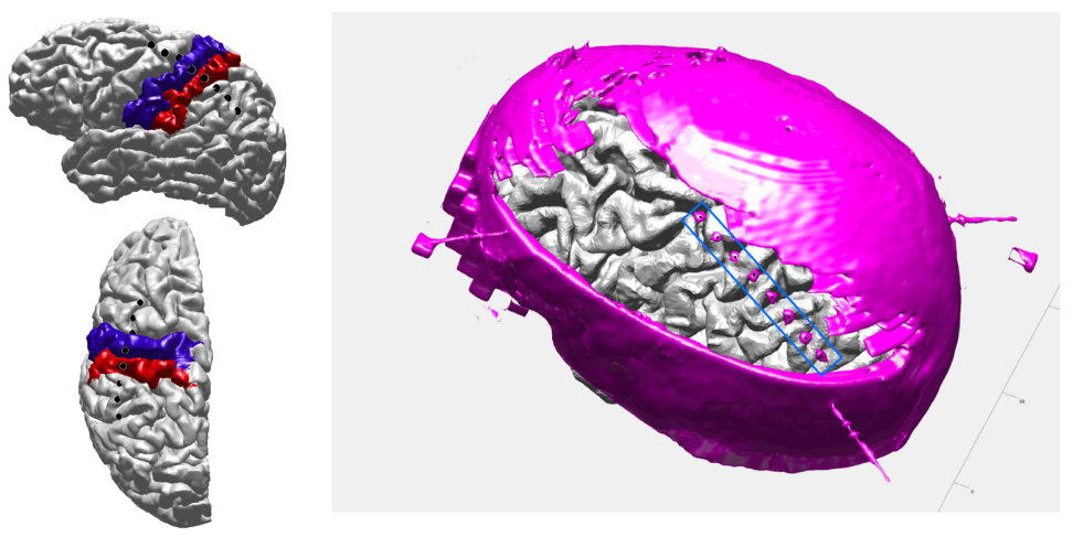
Figure 11.
Illustrates the final step in ECoG localization, showcasing the outcome where the 3D skull and in situ ECoG strips are superimposed and pinpointed. Electrode locations are projected onto and visualized on a reconstructed cortical surface, segmented according to the FS DKT atlas.1.2.3 Transformation of ECoG electrode locations to MNI space and Brian shift correction
The ECoG electrodes, initially measured in Right-Anterior-Superior (RAS) space, are transformed into the standard Montreal Neurological Institute (MNI) space utilizing the Advanced Normalization Tools (ANTS) non-linear Symmetric Normalization (SyN) registration [12]. Each subject's T1 image is registered to the MNI T1 template to compute the necessary transforms. The computed transformations and warp from the registration process are then applied to the ECoG coordinates, effectively converting them into MNI space (Fig. 13). In order to correct for brain shift, we projected the ECoG electrode locations onto the brain surface as described by Hermes et al.[11]
Figure 12.
Transforming ECoG electrode locations from RAS to MNI space using ANTS non-linear SyN registration.1.3 DBS lead localization
For DBS localization, we employ the Lead-DBS toolbox [13], which facilitates the reconstruction of the lead electrode trajectory and contact locations. Utilizing this toolbox, electrode placement can be reconstructed and visualized based on the electrode-induced artifacts on postoperative CT images.
For the DBS lead localization, we utilize T1W, T2W, FGATIR, and 1mm axial postoperative CT images of each subject. These images undergo multiple processing steps within the Lead-DBS toolbox, including coregistration using ANTs Normalization, brainshift correction, and pre-reconstruction. Ultimately, manual alignment of the localized DBS electrode determines the location of each contact point, which is recorded in the ea_reconstruction.mat file (Fig.13). The coordinates of the contact points are reported in both native and MNI space within the ‘ea_reconstruction’ file, which is extracted using custom-made code.
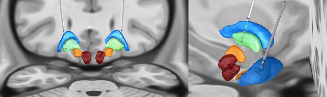
Figure 13.
Illustration of DBS electrode locations in a subject who underwent bilateral globus pallidus internus (Gpi) DBS placement, visualized using the Lead-DBS software, in the MNI space.2. Electrophysiology
Converting raw electrophysiological recordings to the Intracranial Electroencephalography Brain Imaging Data Structure (iEEG-BIDS) format eases data curation and organization, especially for extensive ECoG and DBS data. This standard streamlines the data integration process across different modalities and studies, simplifying analysis and enhancing the investigative potential of the collected recordings[14].
The conversion process within the B(RAIN)ˆ2 pipeline encompasses a series of steps designed to transition raw electrophysiological recordings into a structured iEEG-BIDS format. Initially, a comprehensive review of the existing metadata of raw files is conducted to create a list of 'required' and 'recommended' fields in various components of iEEG-BIDS Metadata, such as the sidecar JSON file, Channel description, and Electrode description, among others. Subsequently, reference documents for metadata common across all patients are generated to ensure a standardized approach to data handling.
To improve data organization, initially recorded raw data is decomposed into the essential functional modules. This segregation addresses the format diversity in acquisition software, such as BCI2000, AlphaOmega, or other acquisition software, which may vary depending on the recording utilities, tasks, and conditions.
2.1 The iEEG Conversion Pipeline
This pipeline employs a series of MATLAB classes that create data objects from raw data (both .mat and .dat files). These objects later will be converted into BIDS-compliant Brain Vision Core Data format, where each recording comprises a .vhdr (Header File), .vmrk (Marker File), .eeg (Data File) file triplet. The intermediary events and data objects enable us to easily add future data formats or output models to the pipeline. This step is crucial for ensuring data compatibility and ease of access in future analytical endeavors.
Within the iEEG Conversion Pipeline, specific segments like the 'Rest' portion of behavioral tasks are seamlessly extracted from principal datasets, enabling the swift creation of customized datasets for distinct secondary projects.
Additional branches of the pipeline collect the experimental and organizational information to populate all the metadata BIDS file structure.
This includes the automated extraction of organization information, task properties, ECoG, and DBS electrode information. The subsequent step involves identifying the appropriate channel configuration, extracting ECoG and DBS attributes and coordinates, and deriving onset time, duration, response time, and other behavioral trial data.
Lastly, all required fields of sidecar JSON file, Channels description, Electrode description, and Coordinate system JSON files and event files are populated in compliance with the iEEG-BIDS format, thus ensuring a well-organized, standardized, and BIDS-compliant dataset ready for further analysis and sharing within the scientific community (Fig. 14).
References
Gorgolewski, K.J., et al., The brain imaging data structure, a format for organizing and describing outputs of neuroimaging experiments. Sci Data, 2016. 3: p. 160044.
Omer Faruk Gulban, D.N., Russ Poldrack, John Lee, Chris Gorgolewski, Vanessasaurus, Satrajit Ghosh, poldracklab/pydeface. 2019, October 31, 2019.
Bidgood, W.D., Jr., S.C. Horii, F.W. Prior, and D.E. Van Syckle, Understanding and using DICOM, the data interchange standard for biomedical imaging. J Am Med Inform Assoc, 1997. 4(3): p. 199-212.
Rosset, A., L. Spadola, and O. Ratib, OsiriX: an open-source software for navigating in multidimensional DICOM images. J Digit Imaging, 2004. 17(3): p. 205-16.
Project, H., Horos DICOM viewer (Version 4.0.0). 2023, sponsored by Nimble Co LLC d/b/a Purview.
Russell, P.H. and D. Ghosh, Radtools: R utilities for convenient extraction of medical image metadata. F1000Res, 2018. 7.
Li, X., dicm2nii. 2023: MATLAB Central File Exchange.
FMRIB Analysis Group, U.o.O., FSL (FMRIB Software Library) version 6. 2023, FMRIB, University of Oxford.
Imaging, M.C.f.B., FreeSurfer Software Suite (version 7.3.2). 2023, Martinos Center for Biomedical Imaging.
Randazzo, M.J., et al., Three-dimensional localization of cortical electrodes in deep brain stimulation surgery from intraoperative fluoroscopy. NeuroImage, 2016. 125: p. 515-521.
Surgical Planning Laboratory, B.a.W.s.H., 3D Slicer Version 5.2.2. 2023, Brigham and Women's Hospital, Harvard Medical School.
Avants, B.B., C.L. Epstein, M. Grossman, and J.C. Gee, Symmetric diffeomorphic image registration with cross-correlation: evaluating automated labeling of elderly and neurodegenerative brain. Medical Image Analysis, 2008. 12(1): p. 26-41.
Hermes, D., et al., Automated electrocorticographic electrode localization on individually rendered brain surfaces. J Neurosci Methods, 2010. 185(2): p. 293-8.
Horn, A. and A.A. Kühn, Lead-DBS: a toolbox for deep brain stimulation electrode localizations and visualizations. Neuroimage, 2015. 107: p. 127-135.
Holdgraf, C., et al., iEEG-BIDS, extending the Brain Imaging Data Structure specification to human intracranial electrophysiology. Scientific Data, 2019. 6(1): p. 102.